

Rotor Winding Description and Types of Turn Shorts
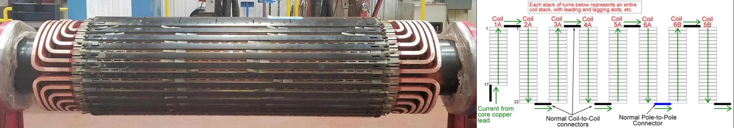
Figure 1 - Rotor with 6 Coils/Pole with both retaining rings and the rotor wedges removed. The #1 coils have 17 turns and Coils 2-6 have 22 turns, producing 254 total turns in the winding. The average length of a turn is about 7.2 m (24 ft). The entire length of the rotor winding is about 1.8 km (1.1 miles). A schematic of the current flow through the turns in Pole A shows where coil-to-coil and pole-to-pole connectors are needed (the connectors are not visible in photograph).
Rotor Winding Description
The rotor windings used in 2- and 4-pole round rotors have their turns arranged in multiple coils for each pole. For each coil, there are two machined slots running down the rotor body that hold the copper turns for that coil (Figures 1 and 2). One slot leads the pole face and the other slot lags the pole face as the rotor rotates past the flux probe. The 2-pole rotor in Figure 1 has 254 turns that have a length of about 1.8 km (1.1 miles). Each of those turns is connected in series to form one long loop for the field current. The North and South poles are distributed along the top and bottom of the rotor in Figure 1.
Figure 2 shows the end-turns of a two-pole rotor with 7 Coils/Pole after the retaining ring was removed. In a coil, the turns will spiral up or down before connecting to the next coil. The copper turns do a U-turn under each retaining ring before returning to the other end in the opposite coil slot. Retaining rings support the weight of the end-turns of the coils and rotor wedges support the weight of the turns in the coil slots. Insulation is used between each turn to prevent short circuits. Blocking is used between the coils in the end-turn regions to prevent coil-to-coil shorts. Slot insulation is installed in the coil slots before the turns and insulation covers the retaining rings so that the winding remains isolated from ground.
How Current Flows Through the Rotor Winding
Figure 3 shows a large two-pole rotor after it was pulled from a generator stator. The yellow overlay lines suggest the current flow around the turns in the visible pole face. The DC current used to excite the rotor winding is provided by some type of excitation system (not shown), In this case, the excitation current gets to the rotor winding through stationary carbon brushes that slide on the two collector rings mounted on the right side of the shaft.
Figure 4 shows the shaft opened up and you can see the axial leads (round copper conductors) that connect to the collector rings. The current travels from one collector ring to an axial lead that runs along the rotor shaft and then passes up through the shaft to the bottom turn of Coil 1 - Pole A (Coil 1A, Figure 5). The bottom turn of Coil 1A travels from the exciter-end region through a Coil 1A slot to the turbine-end retaining ring section and curves around to enter the other Coil 1A slot. The copper turn travels back along rotor slot to the exciter-end retaining ring section and then runs on top of the first turn (starting the second turn in Coil 1A) The turns continue to spiral up the Coil 1A slots until the slots are filled with the desired number of turns and then a coil-to-coil connector allows current to travel from the top turn of Coil 1A to the top turn of Coil 2A (Figures 6 and 7). The current then spirals down the turns used for Coil 2A until it reaches the bottom turn and a coil-to-coil connector allows current to get to the bottom turn of Coil 3A. The process is repeated, with the current alternately spiraling up and then down the turns in each coil until the current reaches the top turn of Coil 7A. A pole-to-pole connector is used to carry current to the top turn of Coil 7-Pole B (Coil 7B) and the whole process is repeated in reverse until the current arrives back at the other collector ring. All of the rotor turns in both poles are connected in one long series loop, from one collector ring to the other.
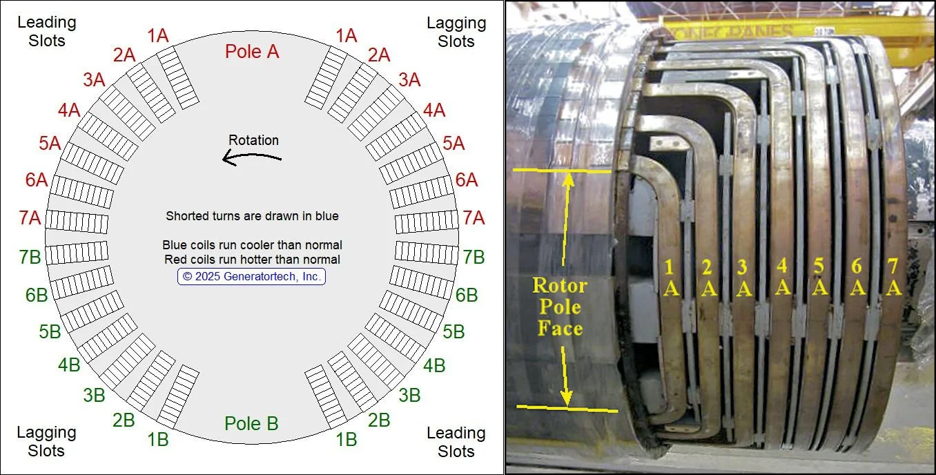
Figure 2 - Rotor cross-section with 7 Coils/Pole and a rotor showing end-turns of winding after the retaining ring was removed. Note the blocking used between the coil stacks to maintain coil separation.
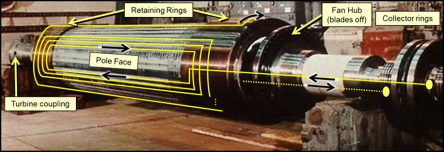
Figure 3 - Large two-pole rotor with a collector rings. Current flows from one collector ring down the shaft (Figure 6) to where it connects to the bottom turn of Coil 1A. The current traverses all the turns used in each coil in Pole A and then passes through a pole-to-pole connector to get to Pole B, where it travels through each turn in that pole before heading back up the shaft to the other collector ring.
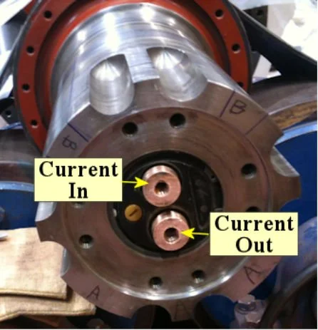
Figure 4 - A rotor shaft opened to see the copper conductors (axial leads) that carry current between the collector rings and starting turn of the #1 coils.
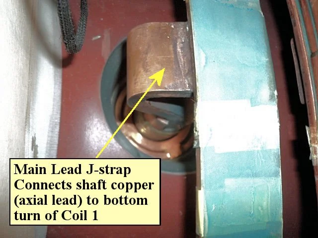
Figure 5 - Main lead connection from shaft copper to bottom turn of Coil 1.
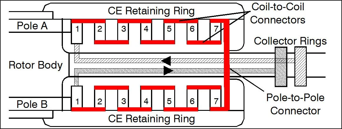
Figure 6 - Diagram showing how coil-to-coil and pole-to-pole connectors link the coils into one series loop. In this case, the coil-to-coil connectors between Coils 1-2, Coils 3-4 and Coil 5-6 are between the top turns of those coils and are visible when the retaining ring is removed (Figure 7). Not shown in this diagram: for each turn in each coil, the turn travels down the rotor body to the turbine-end area in one coil slot and makes a u-turn to return to the collector-ring area in the other coil slot (see Figure 1 above).
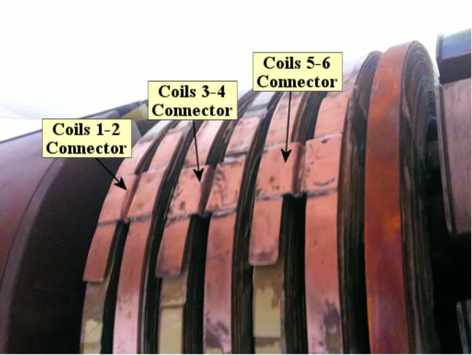
Figure 7 - Coil-to-coil connections in a 7 Coil/Pole rotor winding where the connection from the shaft copper axial leads was to the bottom turns of the #1 coils.
Turn-to-Turn Short - Most Common
The most common type of short seen in rotor windings is the turn-to-turn short (99% of detected shorts), where insulation damage or movement allows contact between two adjacent turns making up part of the coil stack. The high current (hundreds to thousands of amps) used in large generator rotors means that the initial point contact between the turns will produce enough heat to melt copper and create a very low-resistance spot weld. The area of the weld is proportional to the current carried by the winding. The low resistance of the short means that 99.9% of the current will go through the short, effectively removing one active turn from the winding.
Turn-to-turn shorts are common and often produce no operational issues for the generator. The problem with these “silent” shorts is that they raise the temperature of the rotor winding, which makes additional shorts more likely to develop. Therefore, it is important to track the increase in turn shorts over time even if they are not yet affecting operation. Whether problems arise from turn-to-turn shorts is dependent on the percentage of turns shorted out of the winding and the location of the shorts within the winding. For some rotors, even a single short can cause vibration problems that can limit loads.
If turn shorts are affecting operation, a flux probe test can tell which coils have shorts and how many shorts are in each affected coil, facilitating repair efforts.
Figure 8 - Coil winding schematic with five total turns - The short between Turn 3 and Turn 4 allows current to bypass a complete turn (gray) in the coil, leaving 4 active turns and reducing the magnetic field produced by the coil. It doesn’t matter where the short is located along the two turns since the short will always bypass a complete turn and have the same effect in reducing the magnetic field. Therefore, while a flux probe test can determine the number of shorts in a coil, it cannot tell where the shorts developed along the affected turns.
Figure 9 - Alternate diagram illustrating a turn-to-turn short in Coil 3A. The short contact (red T-T) carries the full excitation current, bypassing a complete turn in that coil.
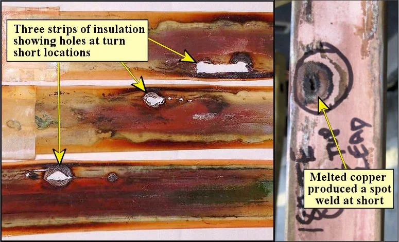
Figure 10 - Examples of damage at turn short locations. Three turn short locations are shown in three strips of interturn insulation. Melted copper damage at the contact point between two turns is shown for one of the turns.
Coil-to-Coil Short
Coil-to-coil shorts are a much more serious type of short, but they occur relatively rarely (1% of detected shorts). A coil-to-coil short involves contact between two adjacent coils in the end-winding region under the retaining rings. If unlucky, a coil-to-coil short will bypass all of the turns used in those two adjacent coils, removing 10-20% of the total turns in the winding at one stroke. Coil-to-coil shorts often cause a forced outage to repair since they normally create serious operational issues (high vibration that can trip the unit, excitation limitations that prevent unit from reaching rated load, and overheating of the rotor winding that quickly causes additional shorts).
Figures 11-15 show an example of a coil-to-coil short in a rotor. This generator developed a sudden vibration problem and could not reach over 50% of full load before vibration rose above trip level. A flux probe test quickly identified the coil-to-coil short as the root cause of the vibration problem. When the retaining rings were removed, the cause of the coil-to-coil short was shown to be due to end-turn distortion that caused contact between the top turns of Coil 2B and Coil 3B (Figure 13), bypassing all 26 turns used in those two coils.
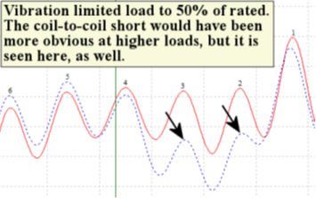
Figure 11 - Lead Slot Overlay Graph that shows the Coil 2B-Coil 3B short. Higher loads would have shown the coil-to-coil short much better than this, but rotor vibration was limiting load to less than 50% full load.
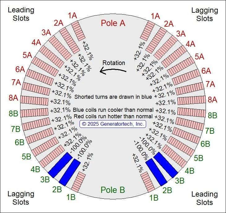
Figure 12 - Rotor cross-section showing location of the 26 total turns bypassed due to Coil 2B-to-Coil 3B short. The combination of a thermal rotor bow and rotor magnetic asymmetry produced severe vibration that limited the unit to less that 50% of rated load.
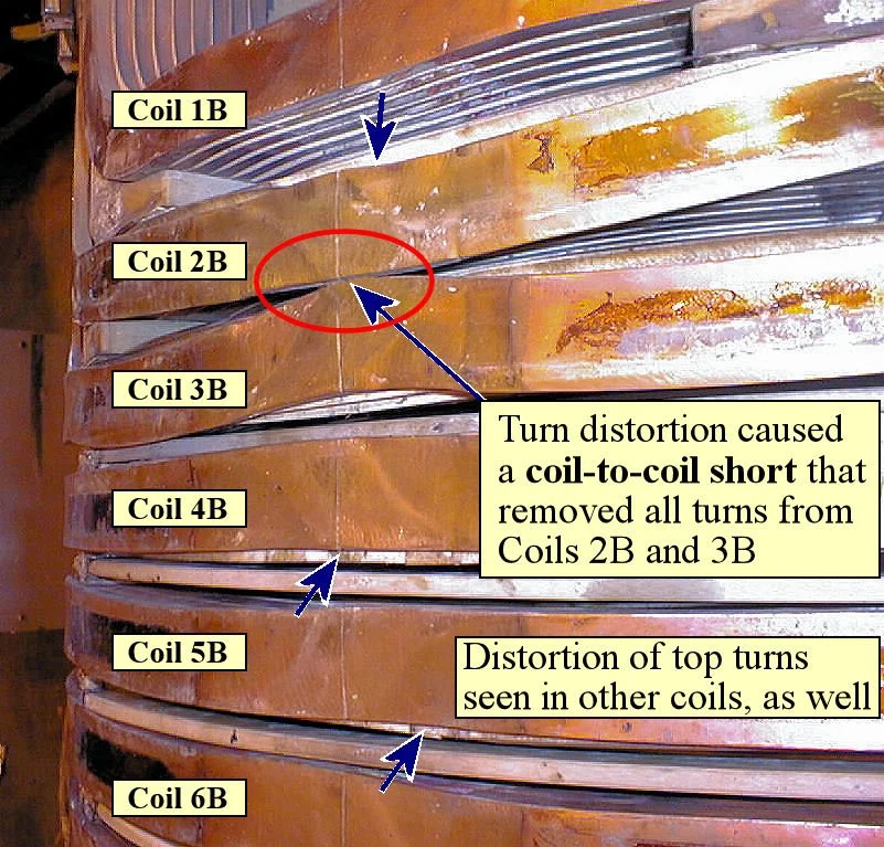
Figure 13 - After the retaining ring was removed, the flux probe test prediction was confirmed. Top turn distortion in Coils 2B and 3B made contact between those two turns, allowing current to bypass all of the turns used in those two coils (Figures 13 and 14).
Figure 14 - Diagram showing how contact between top turns of Coil 2B and Coil 3B allowed current to bypass all 26 turns used in those two coils.
Figure 15 - Alternate diagram illustrating how a coil-to-coil short between top turns of Coil 2B and Coil 3B allows current to bypass all the turns in those two coils.