

Causes of Shorted Turns
Some Common Causes of Turn Short Development
Shorted-turns are the result of failed insulation between individual windings in generator rotors. Stop-Start cycles, line disturbances, contamination, moisture, manufacturer error, and damage during retaining ring installation are some of the reasons insulation fails.
The rotor winding carries currents ranging from hundreds to thousands of amperes, causing its turns to heat and expand during startup and then cool and contract during shutdown. Ideally, all turns within a coil stack would move uniformly; however, this does not always occur. When turn-to-turn movement takes place, significant shear forces are imposed on the thin insulation separating adjacent turns. This insulation can tear or become displaced, allowing the conductors to contact one another and form a shorted turn. The frequency of machine starts and stops directly increases the likelihood of such turn movement and the resulting insulation failure.
The pictures below insulation damage that allowed turn short contacts to form. Effects of the heat produced at the initial contact point is evident on the insulation layers. Examples of copper melting are also shown. The initial contact point will melt and then expand in size until the current density drops below a critical threshold that allows the copper to solidify while still carrying the entire field current. The result is often a spot weld joining the two turns in a very low resistance short. The resistance of the resulting short will be less than 1% of the resistance of the paralleled turn, so more than 99% of the current will flow through the short, effectively bypassing one turn.
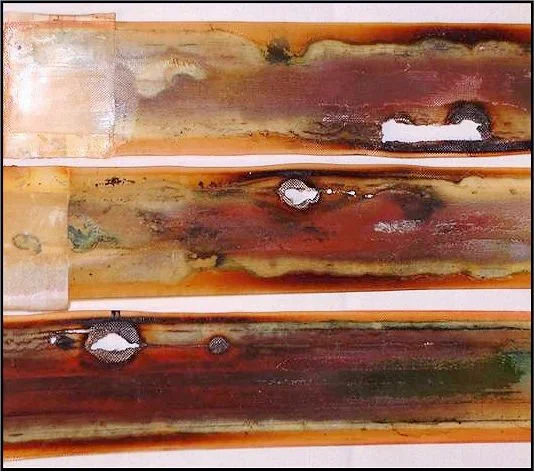
Three separate strips of inter-turn insulation showing holes that resulted in turn shorts.
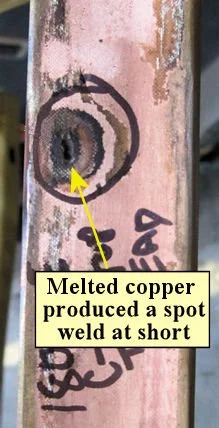
The high current density from the initial point contact between turns produced a spot weld that provided a low resistance short.
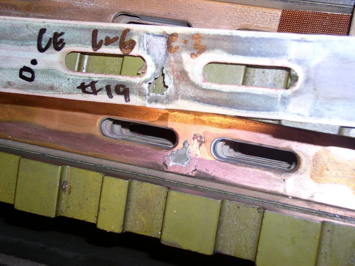
Example showing both the hole in the insulation and the copper damage at a shorted turn contact.
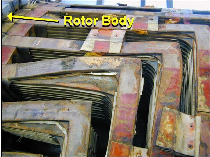
Distortion of the top turns under the retaining ring is fairly common. This pictures shows gross distortion of multiple turns, which resulted in multiple turn shorts. A coil-to-coil short appeared to be imminent.
When turn-to-turn movement occurs, tremendous shear forces act on the thin insulation layer, This can create tears or displace insulation to produce contact that allows current to bypass a turn.
Insulation migration has been a problem in some rotors where the insulation strips were squeezed out from between the turns, resulting in large numbers of shorts developing over a brief period of time. The example below shows the history of turn shorts in three GE Frame 7A6 generators at a plant. The picture is a view of the side of one coil stack with 17 turns and the migration of the white insulation can be seen between many turns near the middle of the stack. The two gas turbine rotors experienced a rapid increase in turn shorts over 4-5 years before they were replaced. The steam turbine rotor showed a slow increase to 3 shorts before its replacement.
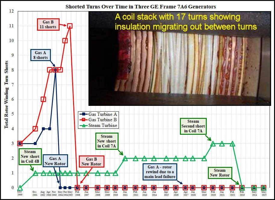
Insulation migration led to a rapid increase in turn shorts in the two gas turbine rotors.
Manufacturing Defects can cause turn shorts.
The high centrifugal forces at synchronous speed (3000 or 3600-RPM) strongly compress the turns in the winding, so any manufacturing defects left on the winding (such as bumps from braze joints) can result in turn shorts as the bumps penetrate through the insulation layer. Any bumps will also aggravate insulation damage if turn-to-turn movements occur, making insulation tears more likely.
Overspeed events have been shown to cause turn shorts. The animation below shows a large 800 MVA rotor than had been tested free of shorts. Six months later, a major grid disturbance led to a 3960-RPM overspeed event (synchronous speed is 3600-RPM). The elevated centrifugal forces on the turns evidently created a new turn short in Coil 6B (only the loads with the best Coils 6 detection sensitivity are shown).
A large 800 MVA generator had tested free of shorts. Six months later, an overspeed event raised rotor speed to 3960 RPM, which results in a new Coil 6B short.
Inadequate or Misplaced Blocking
Problems with the blocking used between coil stacks can allow undesirable turn movement. The example below shows a generator that developed an unexplained jump in both vibration and field excitation levels. The flux probe test very clearly identified a coil-to-coil short between the bottom turns Coils 3A and 4A. That prediction was confirmed when the rotor was rewound. Displaced blocking between Coils 3A and 4A allow the Coils 3A stack to tilt over and the bottom turns of those two coils made contact, bypassing the 20 total turns used in those two coils.
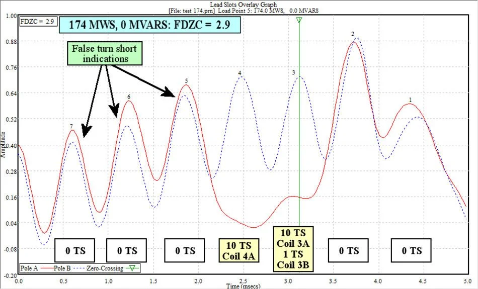
A large jump in vibration was investigated with a flux probe test, which clearly showed a coil-to-coil short between Coils 3A and 4A. The contact was unusual in that it was between the bottom turns of the two coils and it bypassed 20 total turns in the winding.
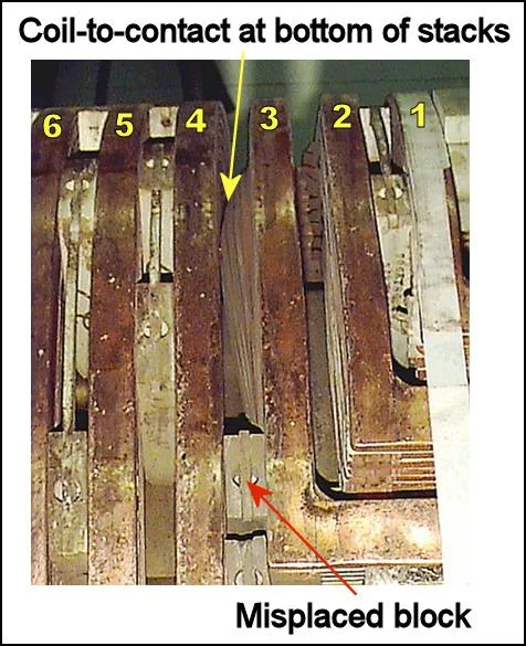
The misplaced block in this image was originally located at the top of the stacks, but it slid down to the corners of end-turns. This allows the turns in Coil 3A to tilt over, allowing contact between the bottom turns of Coil 3A and 4A, bypassing all turns in those two coils (20 total turns).
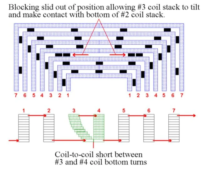
Diagram of how current could bypass all turns in Coils 3A and 4A after the coil-to-coil short between their bottom turns.
Disruption to the normal cooling gas flow to the rotor windings can create hot spots that can lead to turn shorts.. The example below shows a 125 MVA generator that was tested free of turn shorts. About 6 months later, vibration increased and the required field current increased about 15 %. A repeat of the flux probe test showed about 30-35 new shorts in seven separate coils. An examination of the rotor during the subsequent outage found a cooling gas baffle had cracked, severely disrupting cooling gas flow to certain areas of the rotor winding. The turns were overheated and distorted and the insulation was damaged, causing a very large number of turn shorts, with the majority of the shorts affecting the larger rotor coils (Coils 5-7).
Rotor was tested over a wide range of loads and the rotor winding was free of turn shorts.
About six months after the previous test, rotor vibration and field current both increased significantly. The flux probe test showed at least 30-35 new turn shorts. A failed rotor cooling system created hot spots in the winding that damaged insulation and distorted turns, resulting in many new shorts.
High moisture content and foreign material ingress can produce issues that promote turn short development.
If conductive material gains entry to the rotor, turn shorts can be a result. The following case study shows how a water leak in a hydrogen-cooled unit produced a conductive lead-carbonate film over parts of the winding insulation and led to a serious coil-to-coil short.
A water leak in a 450-MVA hydrogen-cooled generator produced to a very high hydrogen dew-point for the unit, which allowed water to condense on surfaces inside the generator when the unit was shutdown. Water condensing on the hydrogen-coolers leached out lead from the lead-tin solder. This lead was then converted to lead carbonate which was blown throughout the generator during operation. The lead carbonate produced a conductive film over a blocking wedge between Coils 6A and 7A which allowed current to flow along the top of the wedge. The heat burned the top of the wedge and converted the top of the wedge to a conductive surface, producing even more heat. Over an inch of the wedge top was burned off and the heat also burned a large hole through the retaining ring insulation. The hole in the retaining ring insulation allowed the top turns of Coils 6A and 7A to make contact with the retaining ring, creating a field ground. The ground detector in the unit was not working and the unit ran for three months with a field ground. The low resistance coil-to-coil short allowed current to flow from the top turn of Coil 6A through the retaining ring to the top turn of Coil 7A, damaging the retaining ring.
The resulting coil-to-coil short bypassed all turns used in both Coils 6A and 7A (18 total turns). The large decrease in active turns in the rotor winding increase field current requirements by 17% and the heat production in each active turn increased by at least 38%. However, because the coil-to-coil short involved the two largest coils in Pole A, the temperature-gradient across the rotor remained modest and the rotor vibration remained below trip level.
This case presents a 450-MVA two-pole rotor with 7 coils/pole that had two coils completely shorted out of the field winding circuit. The top turns of Coils 6A and 7A initially formed a partial short across a blocking wedge that created enough heat to burn through the retaining ring insulation and allowed the top turns of Coil 6A and Coil 7A to form a short through the retaining ring itself (see photo). The resulting coil-to-coil short bypassed all 9 turns in both Coil 6A and Coil 7A (18 total turns). The large decrease in active turns in the rotor winding increase field current requirements by 17% and the heat production in each active turn increased by at least 38%. However, because the coil-to-coil short involved the two largest coils, the temperature-gradient across the rotor remained modest and the vibration remained below trip level.
The field ground was not initially detected due to a faulty ground detection system and the unit ran for a number of months before the field ground was discovered. The resulting damage required a replacement retaining ring to be installed.
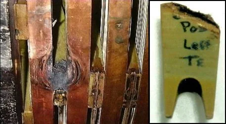
Coil-to-Coil Short: A lead-carbonate film formed over a blocking wedge that allowed significant current to flow between Coils 6A and 7A. The heat burned off over an inch of material from the wedge (right image). The heat burned a large hole in the retaining ring insulation and damaged the top turns of those coils (left image). A coil-to-coil short involving the retaining ring bypassed all 18 turns used in Coil 6A and Coil 7A.
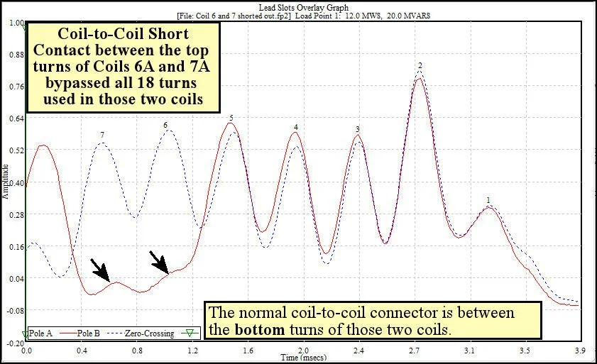
Lead Slots Overlay Graph - shows Coils 6A and Coil 7A completely shorted out of the rotor winding.
Also, note the effect of using magnetic rotor wedges on peak size (Coil 1). Magnetic rotor wedges shunt the magnetic field through themselves and reduce the field the flux probe measures in the air-gap above a magnetic wedge. As a result, peaks from magnetic wedge slots are much smaller than normal.
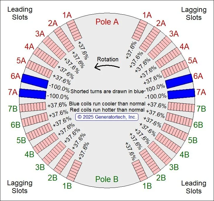
Rotor cross-section - shows all 18 turns in Coils 6A and 7A bypassed by a coil-to-coil short involving the top turns of Coils 6A and 7A. Because the bypassed turns were in the two largest coils of Pole A, the temperature-gradient across the rotor body remained modest and vibration remained below trip level. The field increase raised heat production in the coils without turn shorts more than 37.6% above normal levels.