

Need for Recording a Wide Range of Loads
To detect turn shorts, flux probe waveforms are analyzed by performing a pole-to-pole comparison of coil slot peak heights. However, since multiple factors contribute to coil slot peak heights, the key to an accurate analysis is the isolation of the factor that depends only on the number of active turns in each coil (rotor slot leakage flux).
The factors that do not depend on the number of active turns have two important effects:
1. True turn short detection sensitivity varies with load. At some loads, true turn shorts may not be detectable.
2. False turn short indications that vary with load. At some loads, false turn short indications may appear.
A given load in a synchronous generator produces a waveform with a flux density zero-crossing (FDZC) position that falls within the leading coil slots on the rotor. The MWS Load vs FDZC Position Graph in Figure 1 shows how both real and reactive load changes affect the FDZC position in a unit with a 7 Coils/Pole rotor. Higher real loads (MWS) push the FDZC position to the right towards the smaller rotor coils (Coils 1 and 2). At a given real load (MWS), reducing positive reactive power (MVARS) or increasing negative reactive power will also also push the FDZC position to the right.
There are two important benefits when the FDZC position is aligned with a given coil slot:
1. True turn short indications are maximized for that coil
2. False turn short indications are minimized for that coil
An optimum data set would include waveforms whose FDZC positions were aligned with each rotor coil slot (red filled data points in Figure 1). The Generatortech software will automatically record optimized waveforms as load on the generator is changing.
Figure 1 - MWS Load vs FDZC Position Graph - shows how the FDZC position depends upon both real and reactive power. Startup test data recorded at 0 MVARS until full load was reached. At full MWS load (112.5 MWS), reactive load was varied in both the negative and positive direction.
An optimum test would record a set of waveforms whose FDZC positions closely aligned with each rotor coil (red filled data points). Negative MVARs are often needed at full real load to align the FDZC position with the smallest rotor coils (Coils 1 and 2). Generatortech software automatically records these optimized waveforms as load is changing. The inset shows a waveform that produced a FDZC of 4.0 (55.1 MWS, 0.0 MVARS).
False Negative and False Positive Indications
Recording data using a narrow range of loads and not considering the FDZC position will produce both false negative and false positive indications. We have seen many examples of competitors’ reports that had errors of both types and at least a couple of rotor rewinds were planned that were based upon false turn short indications.
The two case studies shown below illustrate both types of errors in two identical 120 MVA generators at the same power plant. These were two-pole rotors with 8 coils/pole using 9 turns in Coil 1 and 13 turns in Coils 2-8.
Case 1 - False Negative
This rotor had one true turn short in Coil 8-Pole A (Coil 8A). Testing at above 25% of full load could not detect the Coil 8A short, while low load testing clearly detected the short. Competitor’s testing at only full load missed the short in Coil 8A. This rotor had no significant false turn short indications, even thought it was an identical model to that in Case 2.
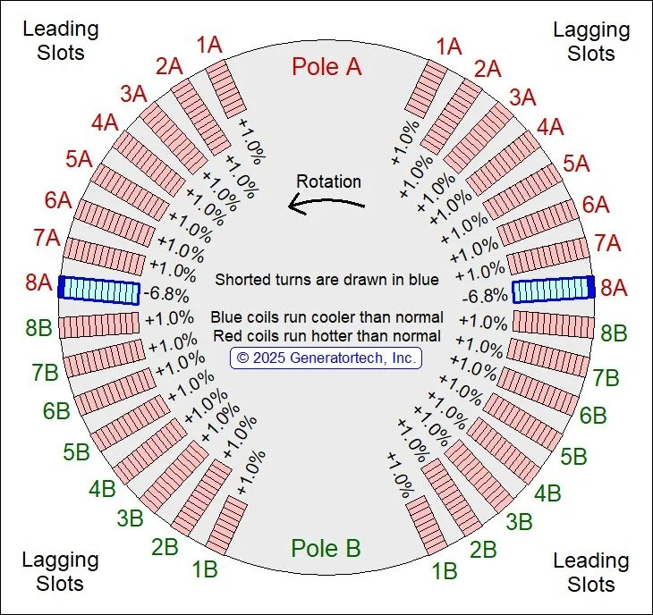
Case 1: Rotor Cross-Section of a 2-pole rotor with 8 Coils/Pole showing the location of a true short in Coil 8A. Competitor’s testing at full load falsely claimed the rotor was free of turn shorts.
Case 1: Lead Slots Overlay Graph Animation - the single short in Coil 8A was not detectable at loads higher than about 25% of full load. However, the short was obvious in low load waveforms. True turn short indications are maximized in waveforms whose FDZC positions are close to alignment with the affected coil.
Case 2 - False Positives
This rotor had false turn short indications in Coil 4 and Coil 5 at both high and low loads.. At medium loads, where the FDZC position was close to alignment with those coils, the false turn short indications disappeared. Competitor’s testing at only full load falsely reported turn shorts in both Coil 4B and Coil 5A.
Although the pattern of false turn short indications remains constant for a given rotor, even rotors from identical generators show different false turn short patterns. In the example below, the first rotor had no significant false turn short indications and the second rotor had two coils with significant false turn short indications. Therefore, false turn short indications cannot be predicted for a given generator. Only by recording a wide range of loads can indications be correctly categorized as true or false.

Case 2: Rotor cross-section showing no true shorts. The false turn short indications seen in Coils 4 and 5 at both low and high loads are modulation artifacts and will not impact normal operation. Competitor’s testing at full load falsely claimed the rotor winding had two shorts.
Case 2: Lead Slots Overlay Graph Animation - the false short indications in Coil 4 and Coil 5 were seen in both low and high loads. In medium loads, where the FDZC positions were closer to alignment with those coils, the false indications disappeared. False indications are minimized in waveforms whose FDZC positions are close to alignment with the affected coil.
Modulation Effects on Coil Slot Peak Heights
The rotor slots have a much higher magnetic reluctance than the iron making up the rotor body and the magnetic field directly above each coil slot will be lower than the field above the iron on either side of the slot. This reluctance-induced change in field strength is the modulation effect across the slot. Modulation effects increase the peak height associated with a coil slot, but they do not reflect number of active turns in the coil. This reduces the true turn short detection sensitivity in the coil, Additionally, pole-to-pole differences in modulation effects are responsible for most false turn short indications.
The same strategy that reduces rotor iron magnetic saturation effects in each coil is also effective in minimizing modulation effects. Since modulation effects are proportional to the magnetic field strength around the coil slot, for a given waveform, the coil that aligns with the flux density zero-crossing (FDZC) position will minimize modulation effects in that coil and that will help to:
Maximize true turn short detection sensitivity
Minimize or eliminate false turn short indications.
The animation below shows a series of waveforms recorded from a temporary flux probe that had been intentionally positioned too close to the rotor surface to emphasize how modulation effects can affect peak heights. In this example, the peak heights in coils far from the FDZC are virtually all due to modulation effects. For coils aligned with the FDZC, modulation effects are minimized and the peak height s almost entirely due to rotor slot leakage flux. Rotor slot leakage flux is proportional to the number of active turns in the coil and is the factor needed to quantify the number of turn shorts in a coil.
In the animation below, note that each coil displays its minimum peak size when the coil is aligned with the FDZC position. The FDZC position which marks the smallest magnetic field around the rotor (dotted blue curve). Away from the FDZC position, the field gets stronger, and modulation effects produce larger and larger peak heights. Note the large peaks in the pole faces (not numbered) that are due to amortisseur winding slots. The amortisseur slots are not carrying any current in these waveforms, so their peak sizes are 100% modulation effects.
An ideal test would include a set of waveforms whose FDZC positions were aligned with each coil in the rotor, optimizing true turn short detection sensitivity and minimizing false turn short indications.
Modulation Effects on Peak Heights - This test was performed with a temporary flux probe intentionally adjusted to be too close to the rotor surface in order to emphasize modulation effects on coil slot peak heights. For a given coil, the peak size will be at a minimum when the FDZC (vertical green line) is aligned with that coil slot since that condition minimizes the modulation effects for that coil. The peak size of coils far from the FDZC are almost entirely due to modulation effects, reducing detection sensitivity for true shorts.