

Setting Up a Shorted-Turn Condition Monitoring Program
When planning the installation of permanent probes, the following advance planning subjects should be addressed.
Critical machine dimensions such as rotor outer diameter (O.D.), retaining ring O.D., and stator core I.D. need to be supplied to Generatortech so the flux probe can be manufactured before assembly. Generatortech will provide a drawing showing which dimensions must be supplied. If desired, Generatortech personnel will take the dimensions.
Magnetic wedges in the rotor coil slots reduce the air-gap slot leakage flux signal. Thus, shorted turn detection sensitivity is reduced in these slots. If plans are being made to assemble an air-gap probe, extra effort and possibly cost should be expended to ensure that all wedges in the leading slots at the axial position of the flux probe are non-magnetic. On some fields, this may require purchasing 2 to 4 non-magnetic wedges from the Original Equipment Manufacturer. The wedges would be used to replace the magnetic wedges near the turbine end in the slots leading the pole.
Discussions with Generatortech should be made early in the planning stages.
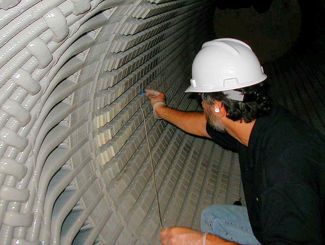
Initial placement of flux probe on stator wedge, Probes are normally installed on the turbine-end of stator, using a 3:00 or 9:00 slot position to accommodate rotor removals and installations.
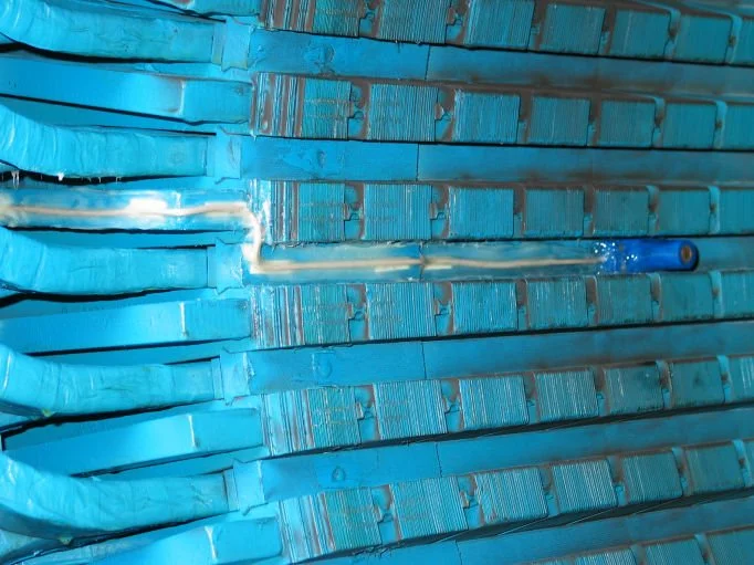
Flux Probe glued and doweled onto stator wedge. The flux probe cable is routed out of the stator core along the wedges, then transitions to a pressure plate between the stator bars get through the stator end-windings. The probe cable is routed to the inside of the the generator casing along solid surface and is then epoxied from start-to-finish.
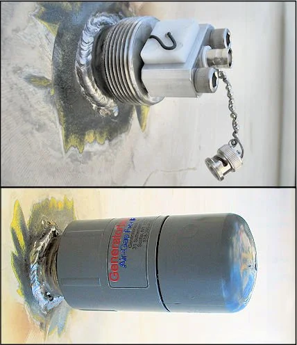
Welded-on casing gland with BNC connection that is suitable for both hydrogen- and air-cooled generators. The flux probe cable is spliced and soldered to the casing gland leads on the inside of the generator.

NEMA-4 Termination Box is suitable for air-cooled units. The flux probe cable is connected to the BNC assembly inside this termination box.