

Case Studies
Generatortech, Inc. has extensive experience in analyzing rotor winding shorted turns.
Since 1989, over 6,000 Generatortech flux probes have been installed in generators worldwide.
We have a large and growing database of test data on these units. Many generators with shorted turns detected using our equipment have been taken apart during this time period and we have been gratified to have had our shorted turn predictions verifed.
This section provides a look at a few case studies that forcefully make the case for flux probe monitoring of your rotors. If you are responsible for making maintainance decisions for your generator sets, you owe it to yourself to arm yourself with the only tool that can quickly and accurately assess the condition of your rotor's insulation system before coming off-line.
While off-line tests are valuable, they can not detect speed-dependent shorted turns (shorts that only develop when the rotor is at rated speed). Tests in balance-pits, with our equipment, has confirmed the presence of speed-dependent and temperature-dependent shorted turns in a number of cases. These tests allowed the service companies to repair the speed-dependent shorted turns at their facility before shipping the rotors back to their customers, saving enormous time and expense.
Case 1: True Turn Short Detection Sensitivity with Changes in Load
This 820 MVA generator had a two-pole rotor with 8 Coils/Pole using 7 turns in Coil 1 and 8 turns in Coils 2-8. There were single turn shorts in Coil 1A, Coil 3B and Coil 6B. If testing had been done only at full load, the short in Coil 6B would have been missed. If testing had occurred only at low load, the shorts in Coils 1A and 3B would have been missed.
Lead Slots Overlay Graph Animation - The turn shorts in Coil 1A and Coil 3B are not detectable in the lower load waveforms and the short in Coil 6B is not detectable in the higher load waveforms. The need for recording a wide range of loads is clearly demonstrated. The inset graphs show the same rotor after a rewind successfully repaired all three turn shorts.
Case 2: True short in Coil 8B not visible at higher loads, multiple false shorts except near FDZC position
A large 850 MVA generator with 8 Coils/Pole using 5 turns in Coil 1 and 7 turns in Coils 2-8 had a true turn short in Coil 8B that was not detectable until the power decreased below about 50% of rated load. Quite a number of false shorts were seen, but all of those false indications disappeared when the FDZC position was aligned with the coil. Note the higher load waveforms show false turn short indications that are larger than the true turn short indication in Coil 8B.
Lead Slots Overlay Graph Animation - shows true and false turn short indication variation with load. At higher loads in this case, false indications in some coils were larger than the indication of the true short in Coil 8B, demonstrating the need to record data over a wide range of loads.
Case 3: Single Turn Short in a Four-Pole Rotor
This case presents a large nuclear generator with a four-pole rotor that has a single turn short in Coil 4-Pole A. The short was not well detected when operating at high loads when the flux density zero-crossing (FDZC) position was far from Coil 4. At low loads, with the FDZC position closer to alignment with Coil 4, the short in Coil 4A was obvious. The single short increased the required field current by 1.0% in order to produce the same rotor magnetic field strength with few active turns in the winding. The extra current increased heat production in each active turn by a little more than 2%. The reduction in active turns in Coil 4A reduced heat production in that coil by 12.5%. The reduction in the magnetic field over Pole A as compared to Pole C created a Once/Revolution vibration that tracked instantaneously with changes in field current.

Rotor cross-section - showing location of the Coil 4A slots with a single turn short out of 7 total turns. The short created a magnetic asymmetry about the rotor, with Pole C being stronger than Pole A.
Lead Slots Overlay Graph Animation - large nuclear 4-pole generator with a single short in Coil 4-Pole A. The short is not well detectable at high loads, but is easily detectable at low loads.
Case 4: Repair of Coil 8A Turn Short
The images below show a large 680 MVA generator with 8 coils/pole and 5 turns in Coil 1 and 6 turns in Coils 2-8. A turn short in Coil 8A was not clearly detectable at full load, but was obvious at low loads. The rotor was rewound and the Coil 8A short was repaired, however, full load data could not confirm the repair. Low load data was needed to see that the rewind was successful.
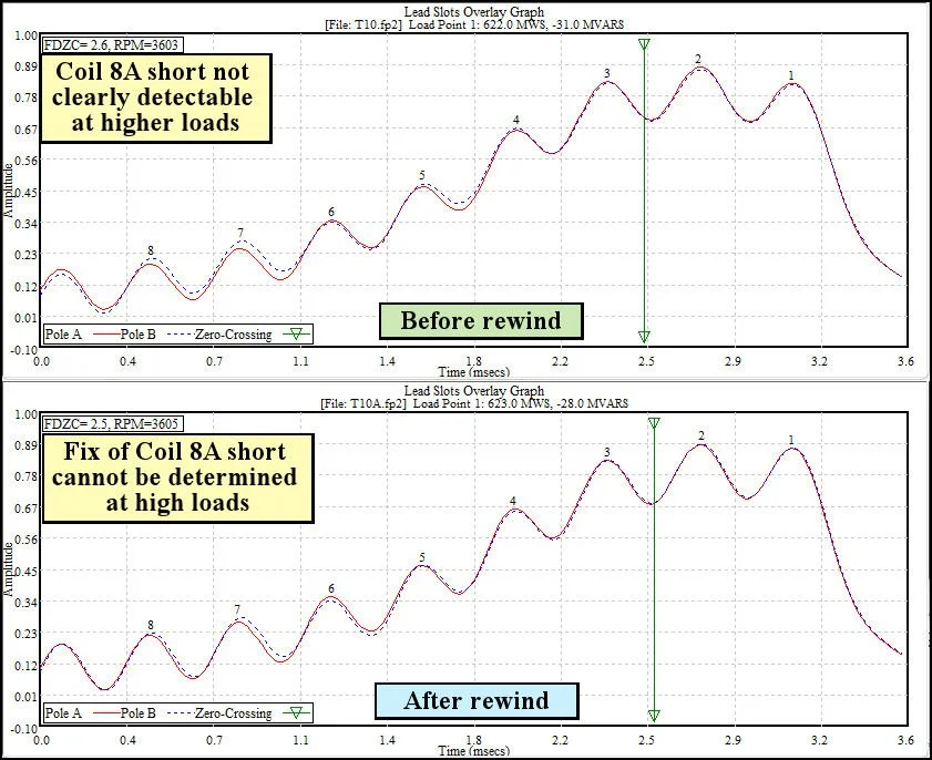
High Load Data - the Coil 8A turn short was not clearly detectable at high loads.
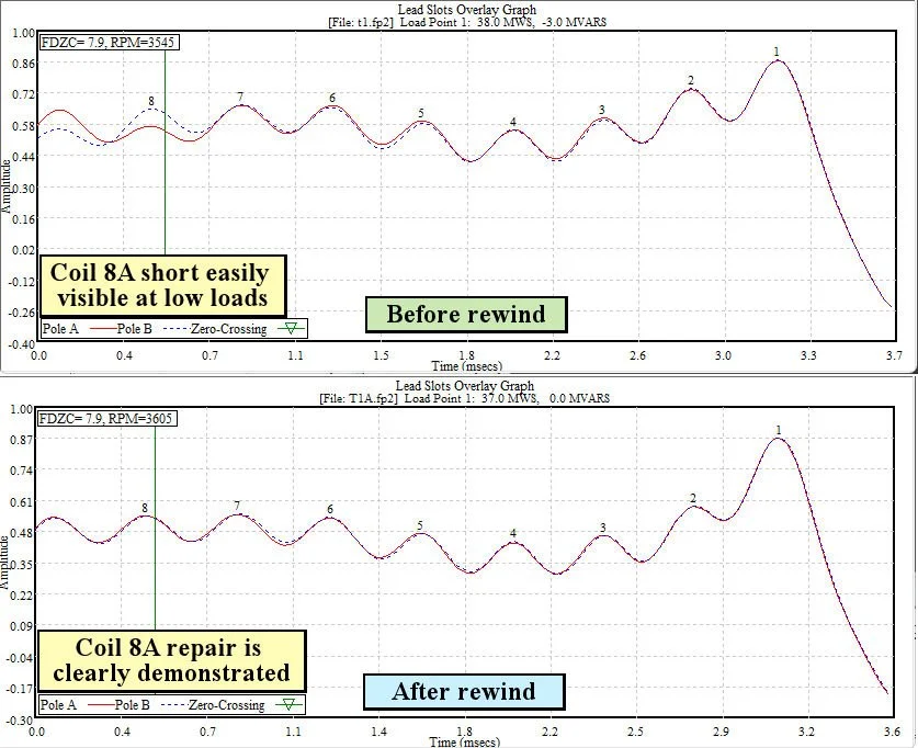
Low Load Data - clearly shows that the Coil 8A turn short was successfully repaired during the rotor rewind.
Case 5: Coil-to-Coil Short between Coil 6A and Coil 6B
This generator had been tested free of shorts a few months earlier, but the utility complained that field excitation had increased by close to 20%, even though rotor vibration had not increased. A flux probe test proved that 58 turns (29 turns in each coil) were shorted out of the rotor winding due to a coil-to-coil short between the top turns of the two #6 coils. The symmetry of the short condition did not produce a temperature-gradient or a magnetic-asymmetry around the rotor, so there was no impact on rotor vibration. However, the observed 20% increase in field excitation was predictable given the 58 bypassed turns. The excitation needed to increase that amount to produce the same rotor magnetic field with fewer active turns in the rotor winding. The heat production in each active turn increased at least 44.7% above normal.
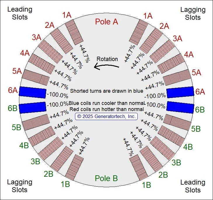
Rotor cross-section showing the location of the 58 bypassed turns caused by the coil-to-coil short (29 turns in both Coils 6A and 6B). The short resulted from contact between the top turns of the two #6 rotor coils.
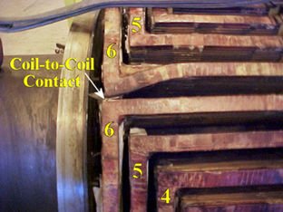
After the retaining rings were removed, the turn distortion responsible for the coil-to-coil short became obvious.
The animation shows the All Slot Overlay Graphs from the test because it clearly show the symmetrical nature of the coil-to-coil short. Even though 58 turns were being bypassed, the high load waveforms were not showing a coil-to-coil short. However, at low loads, the coil-to-coil short was obvious.
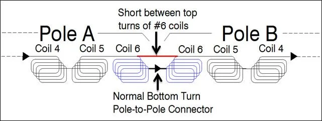
A winding diagram indicating current flow shows how contact between the top turns of the #6 coils (red) will allow current to bypass all turns used in those two coils (normal pole-to-pole connector is located between the bottom turns of the two coils).