

Rapidly Increasing Magnetization (RIM) Waveforms
Rapidly Increasing Magnetization (RIM) waveforms are off-line waveforms recorded during startups when the rotor field is initially excited. During this period, the rotor magnetic field strength is rapidly increasing. Since the bypassed turns created by turn shorts are still electrically contiguous, a changing magnetic field will induce a counter-current in those turns, producing a magnetic field that opposes the field from the active turns (Lenz’s Law). This bucking flux strongly reduces the field above the affected coil slots, producing much smaller peaks than are seen in the on-line data. As a result, the calculated number of turn shorts is strongly amplified over what is seen in the on-line waveforms.
The amplification of turn shorts is seen almost equally in all rotor coils, so we can get confirmation of turn shorts from Coil 1 to the largest coil in RIM waveforms. In addition, the amplified indications are seen equally well in both the leading and lagging coil slots. Therefore, we often display RIM waveforms using the All Slot Overlay Graphs. Since the amplification of turn shorts in RIM waveforms requires the large induced counter-currents in the bypassed turns, the technique will not amplify false turn short indications.
RIM waveforms cannot be used to quantify the number of shorts that are in a coil, but they provide strong confirmation of the shorts seen in the on-line data.
RIM waveforms are especially valuable when dealing with symmetrical turn shorts. Symmetrical shorts are when the same coil on each pole has the same number of shorts. Since the peak heights being compared are similarly affected, symmetrical shorts are much more difficult to detect. However, the strong amplification of the turn short indications in RIM waveforms can make symmetrical turn short conditions obvious.
The Generatortech software automatically records RIM waveforms during the initial excitation period.
Two-pole rotor with a symmetrical turn short condition
The example below shows a 44.5 MVA GE generator with a two-pole rotor and 5 coils/pole with 16 turns in each coil. The on-line test found a single turn short in Coil 4B and there was a possibility that there were symmetrical shorts in the #3 coils (Figure 1). Since symmetrical shorts have an equal effect on both peaks, a straight-forward pole-to-pole comparison will not detect the shorts. When using on-line waveforms, a more involved comparison is often needed to detect symmetrical shorts. A comparison with data recorded before the symmetrical shorts developed is extremely useful, as is modeling the expected peak heights using the adjacent coils. However, a RIM waveform can easily detect symmetrical shorts since both peak heights are so much smaller than normal.
In the RIM waveform’s Lead Slots Overlay Graph, the amplified turn short indications clearly show the turn short in Coil 4B and the symmetrical shorts in Coils 3A and 3B (Figure 2). The turn short indication in Coil 4B was amplified about the same as the indications for Coils 3A and 3B. The All Slots Overlay Graph of the RIM waveform shows that the amplified indications are seen equally well in both the leading and lagging coil slot regions.
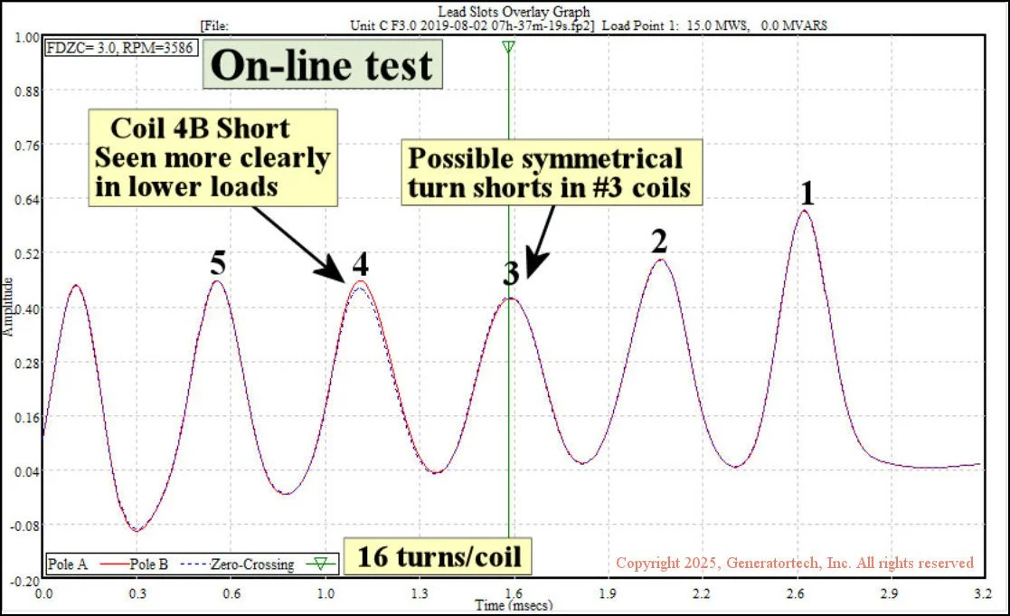
Figure 1 - Lead Slots Overlay Graph - Online waveform at 15 MWS, 0 MVARS had near optimum detection sensitivity in the #3 coils. The waveform shows a possible symmetrical short condition in the #3 coils, but we couldn’t be sure using just this waveform. A turn short in Coil 4B is evident in this waveform, but lower loads with the FDZC aligned with the #4 coils showed larger turn short indications (not shown).
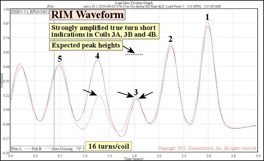
Figure 2 - Lead Slots Overlay Graph - RIM waveform recorded during the initial excitation period when the rotor magnetic field was rapidly increasing. The much larger decrease in peak heights in RIM waveforms made the symmetrical shorts in Coils 3A and 3B obvious. The short in Coil 4B shows the same large decrease as the shorts in Coils 3A and 3B.
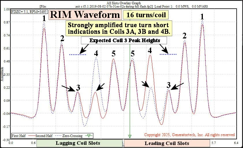
Figure 3 -All Slots Overlay Graph -turn shorts in RIM waveforms show equal indications in both the lagging and leading slots (NOTE: curve lines swap colors in the lagging slot region).
Four-pole rotor that developed three shorts
The case study below shows a large nuclear four-pole 1000 MVA Westinghouse generator that initially had two shorts, with single shorts in Coil 2C and 4A. The fact that the shorts were in opposite poles meant the rotor maintained a high degree of magnetic symmetry (Figure 4) and the unit had no vibration issues. In 2009, a new short developed in Coil 1A. With two shorts in Pole A and one in Pole C, a magnetic asymmetry was created and vibration levels increased. A rotor rewind was successful and vibration decreased back to normal levels.
The Lead Slots Overlay Graph animation shows a complete test from 2008 when the rotor had two shorts. The Coil 4A short was easily detectable at lower loads, but was not detectable near full load. Full load waveforms after the rotor developed the Coil 1A short and after a rotor rewind are also included.
The All Slots Overlay Graphs (Figure 5) contrast an on-line full load waveform with a RIM waveform recorded when the rotor was running with three turn shorts. The RIM waveform definitively identified all three coils with turn shorts, supporting findings from the on-line dataset. By itself, the RIM waveform could not be used to quantify the number of shorts in each coil - the on-line data was needed to determine that each affected coil had one turn short..
Figure 4 - Rotor cross-section animation. The rotor initially had two shorts, with single shorts in Coil 2C and 4A. Being in opposite poles, the magnetic unbalance was very small and vibration was not an issue. In 2009, a new short developed in Coil 1A. With two shorts in Pole A and one in Pole C, the magnetic asymmetry created a vibration issue. After a rotor rewind, the rotor tested short free and had no vibration problems.
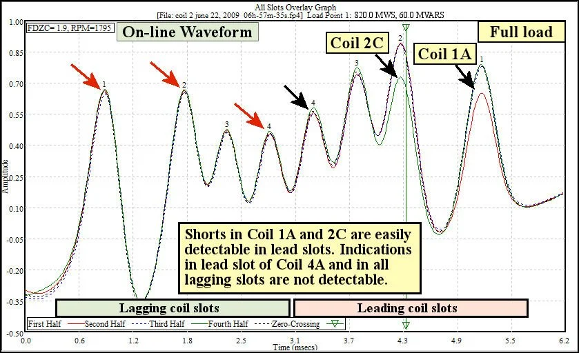
On-line Near Full Load Waveform- All Slots Overlay Graph - the turn shorts in Coil 1A and Coil 2C are easily detectable in the leading coil slots, but because of magnetic saturation and modulation effects, the short in Coil 4A is not detectable. For the same reasons, none of the shorts are detectable in the lagging coil slots.
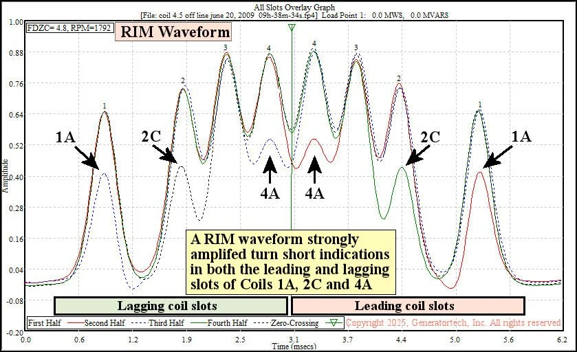
RIM Waveform - All Slots Overlay Graph - shows strongly amplified turn short indications in all three coils, with equal detection sensitivity in the leading and lagging slots. This waveform confirmed the location of the three shorts seen in the on-line data, but it cannot be used by itself to quantify the number of shorts in each coil.